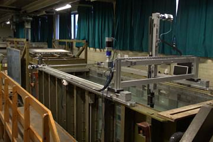
Working Section of the recirculating water channel
Filled with 90,000 litres of water the channel is capable of producing accurate flow speeds from 1 m/s up to 6 m/s allowing precise experimental data measurement. The working section is 3.7 m long, 1.4 m wide, and has an adjustable floor to give water depths between 0.15 and 0.85 m. A brass honeycomb flow-straightener in combination with a contraction upstream of the open channel working section ensures a uniform velocity profile at the section entry, while a water jet injection at the start of the working section adds flow to the free surface to maintain the uniform velocity profile at the surface.The versatility of the facility is demonstrated by its capabilities to analyse external aerodynamics of bodies submerged within the working section such as aircraft or chimney stacks, to analyse the motion and forces of bodies on the water surface such as ship hulls, and to perform cavitation studies in which a lid is fitted to the working section.
Most recently the water channel has been used to measure the flow over the largest ship class ever built for the Royal Navy, the Queen Elizabeth Class aircraft carriers [1]. The aerodynamic environment in which aircraft have to land on the ship can be highly unsteady. To reduce the risk to pilots, the flow over the ship is modelled using Computational Fluid Dynamic, CFD, and integrated into a flight simulator in which the pilot can experience the effect of the unsteady environment.
The water channel was used both analyse the flow over the aircraft carrier and to obtain experimental validation data to provide confidence in the CFD models. A 3D printed model of the ship was created and attached to the floor of the working section. Mean and unsteady velocity measurements were then measured at predetermined points using Acoustic Doppler Velocimetry, ADV, a technique which detects small variations in the acoustic signal frequency arising from the Doppler effect, to measure the velocity in three components. The ADV probe emits a signal from the acoustic transmitter, which is then reflected to the four receivers from particles moving with the flow. The sample volume is 6 mm in diameter, 7 mm long and located 50 mm in front of the transmitter. While mean velocity measurements may be obtained in all three components of the flow to within 1% accuracy, turbulence may only be measured in the direction of the transmitter due to Doppler noise. Using two directional probes the turbulence can be measured in the vertical and lateral directions. The probe provides measurements up to a sampling rate of 200 Hz.
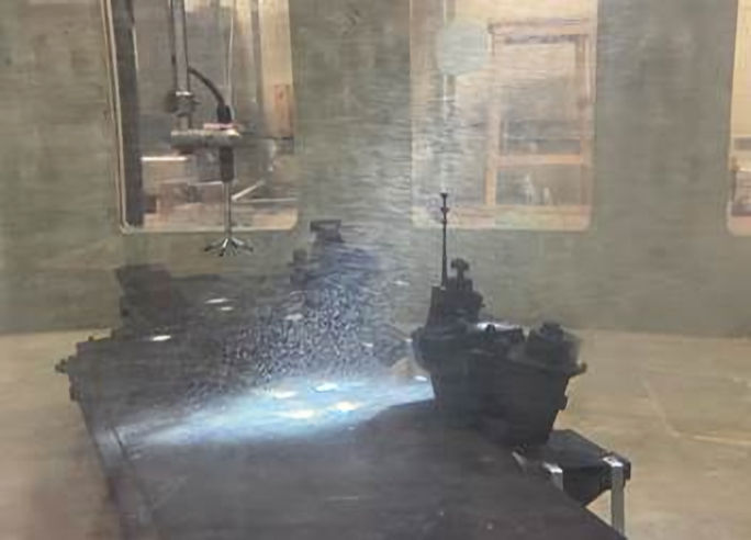
ADV over Queen Elizabeth Class aircraft Carrier
To achieve positional accuracy and repeatability of each measurement within the water channel, the ADV probe is attached to a three-dimensional motorized programmable traverse providing positional accuracy of 0.1 mm. The traverse can be modified to hold and move other instruments or models within the flow accurately.
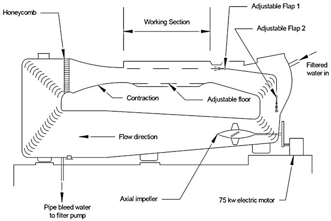
Schematic of the recirculating water tunnel
[1] Watson, N. A., Kelly, M. F., Owen, I., Hodge, S. J., and White, M. D., “Computational and experimental modelling study of the unsteady airflow over the aircraft carrier HMS Queen Elizabeth,” Ocean Engineering, Vol. 172, No. 1, 2019, pp. 562-574. doi: 10.1016/j.oceaneng.2018.12.024
Back to: School of Engineering